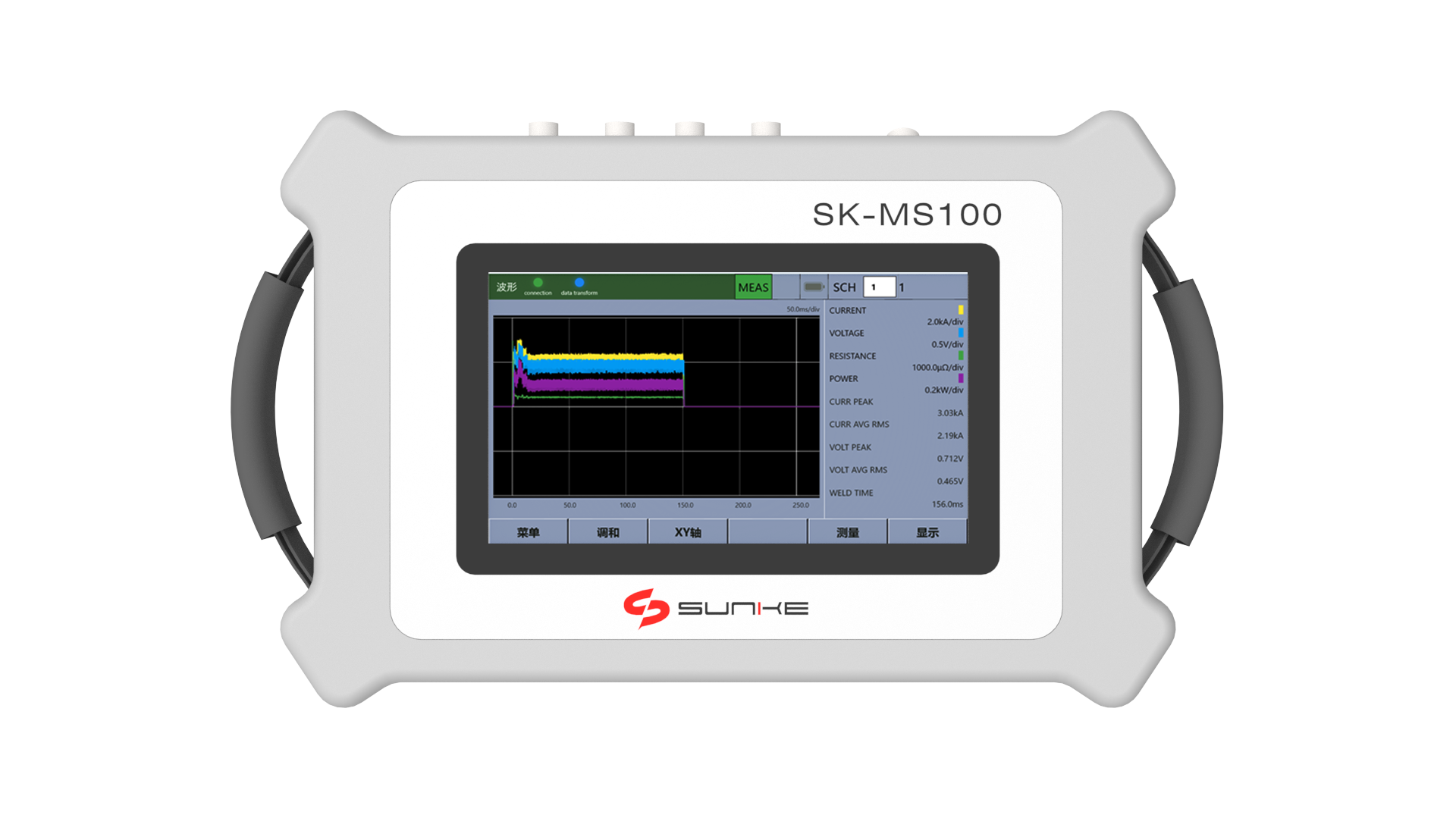
Weld quality problems do not always leave visible marks on a finished component. A joint may look acceptable while its electrical signals reveal inconsistent heating, unstable contact resistance, or variations between welding cycles. A resistance weld checker helps engineers examine these process conditions, but its measurements are sometimes misunderstood or treated as direct proof of joint strength.
Understanding what monitoring equipment can and cannot reveal allows production teams in automotive, battery, electronics, and general manufacturing to make better decisions about process control and quality inspection.
Misconception: One Measurement Can Explain Every Welding Problem
Welding quality depends on several interacting variables, including current, voltage, electrode force, weld duration, material properties, and surface condition. A single measurement rarely explains every defect. For example, an unexpected current reading may indicate a change in the power supply, poor electrode contact, or a shift in the workpiece assembly. Engineers need to examine the surrounding process conditions before deciding on corrective action.
Electrical resistance also requires careful interpretation. Although resistance changes can provide useful information about contact conditions and heat generation, the relationship between resistance and joint quality is not always straightforward. Material thickness, electrode wear, and surface contamination can produce different signal patterns, even when the welding settings remain unchanged.
A more reliable approach combines multiple measurements with inspection results and established process limits. Monitoring current alongside voltage, power, resistance, or electrode pressure can provide a broader view of the welding cycle. This method helps technicians investigate possible causes instead of treating every unusual reading as evidence of the same underlying fault.
Misconception: Monitoring Equipment Works the Same With Every Welding System
Resistance welding installations differ in power supply design, operating frequency, pulse sequence, and electrical configuration. Equipment suitable for one production line may require different sensors or measurement settings on another. Compatibility should be confirmed before installation, particularly when existing machinery has been modified or combines components from different manufacturers.
The resistance welding transformer affects the electrical characteristics of the welding circuit by converting the supply voltage and delivering high current at a suitable voltage for the application. Its specifications and operating conditions influence how current and voltage measurements should be interpreted. Engineers should account for the transformer, secondary circuit, sensor arrangement, and welding controller when configuring a monitoring system.
Another common misunderstanding concerns AC and DC measurement. Some applications use alternating current, while others rely on direct current or sequences involving multiple pulses. Measurement equipment must support the relevant waveform and analysis method. Single-pulse evaluation may be sufficient for one process, whereas multi-pulse or selected-pulse analysis can provide more useful information when individual stages require separate examination.
Misconception: More Data Automatically Produces Better Quality Control
Collecting additional parameters does not necessarily improve decision-making. If operators receive large amounts of data without clear limits or interpretation guidelines, meaningful changes can become difficult to distinguish from normal variation. Effective monitoring begins with identifying which variables relate directly to the process risks and quality requirements of a particular component.
Data resolution is another consideration. A system that samples too slowly may miss short-lived changes during a brief welding cycle. Faster sampling can reveal more detail, but its value depends on whether the recorded signals help engineers answer specific technical questions. Appropriate measurement settings should reflect weld duration, pulse characteristics, and the level of detail required for fault analysis.
Sunke’s resistance welding monitors support multi-parameter measurement of current, voltage, power, resistance, and pressure, with AC/DC measurement options that include single-pulse and multi-pulse analysis. These functions can help technical teams examine different stages of a weld cycle. Before adopting such equipment, manufacturers should confirm that the available channels and measurement modes match their actual welding process rather than assuming that every function is necessary.
Misconception: A Normal Reading Proves That a Weld Is Defect-Free
Electrical monitoring provides valuable evidence about process stability, but it cannot independently confirm every aspect of a finished joint. A weld may fall within established electrical limits while still having a mechanical defect caused by material conditions, poor fit-up, electrode alignment, or other factors. Process measurements should support a wider quality-control plan rather than replace all other inspection methods.
A normal monitoring result does not guarantee that a weld is free from internal defects. For a clearer understanding of the role and limitations of monitoring equipment, see how resistance welding monitoring helps reduce weld defects as part of a broader quality-control process.
Destructive testing, metallographic examination, and suitable mechanical tests can help validate the relationship between monitored signals and actual joint performance. Once this relationship has been established for a specific application, engineers can use monitoring data to identify deviations more efficiently. Periodic validation remains important because electrode wear, tooling changes, and material batches may affect the process over time.
Thresholds also need regular review. Limits developed during initial commissioning may become unsuitable after changes to production speed, workpiece design, or welding parameters. Quality engineers should compare monitoring records with inspection findings and revise process limits when supported by evidence. This practice helps prevent both unnecessary alarms and missed warning signs.
Conclusion
Resistance welding inspection becomes more effective when measurements are interpreted in context rather than treated as isolated pass-or-fail answers. Engineers benefit from understanding electrical behavior, confirming equipment compatibility, selecting meaningful parameters, and validating monitoring results against actual joint performance.
A resistance weld checker is most useful when its data supports clear decisions about troubleshooting and process stability. Manufacturers evaluating Sunke can assess the available measurement functions against their welding configurations, quality objectives, and integration needs, allowing technical requirements to guide the final equipment decision.